Adding Collisions and Inertia
In it’s current form, the URDF file is perfectly serviceable for real hardware. Links can contain additional Collision and Inertial information, these are primarily needed for simulations.
For more information, it is highly recommended you visit the official documentation about URDF Links.
Collisional Information
For Boxes, Cylinders and Spheres, the same primitive geometry can be used for collisions and inertia. An example would be the box for the base_link:
11<link name="base_link">
12    <visual>
13        <geometry>
14            <!-- Box is defined as xyz lengths in m -->
15            <box size="0.5 0.4 0.3"/>
16        </geometry>
17        <!-- Centre of box relative to link -->
18        <!-- Leave as "0 0 0" for box centre at link origin -->
19        <origin xyz="0.15 0 0.10" rpy="0 0 0"/>
20    </visual>
21
22    <collision>
23        <!-- Same geometry and origin as visuals -->
24        <geometry>
25            <box size="0.5 0.4 0.3"/>
26        </geometry>
27        <origin xyz="0.15 0 0.10" rpy="0 0 0"/>
28    </collision>
29</link>
For meshes, the additional computation required to compute a collision for all the additional vertices is usually not worth it, compared to the quicker calculations for a more simple primitive. The general rule is, unless you have a really good reason not to, use a primitive for collision calculations.
31<link name="lidar_link">
32    <visual>
33        <geometry>
34            <!-- Mesh file uses "package://<packagename>/<path>" -->
35            <!-- Scale "x y z" can be useful when converting to mm <-> metres -->
36            <mesh filename="package://example_urdf_description/meshes/Generic_100mm_lidar.stl" scale="1 1 1"/>
37        </geometry>
38        <material name="uom_yellow"/>
39        <origin xyz="0 0 0" rpy="0 0 0"/>
40    </visual>
41
42    <collision>
43    	<geometry>
44            <cylinder length="0.08" radius="0.08"/>
45        </geometry>
46        <origin xyz="0 0 -0.015" rpy="0 0 0"/>
47    </collision>
48</link>
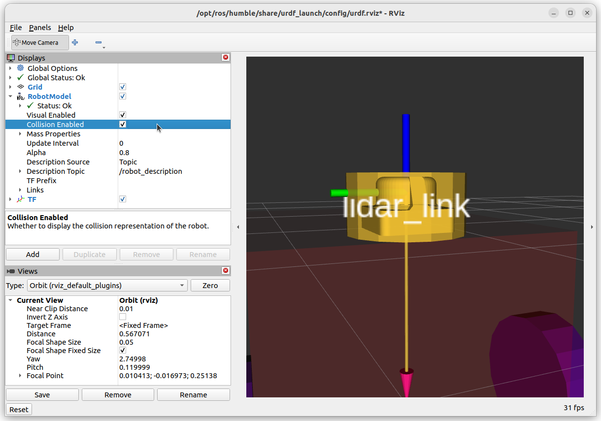
The picture above shows how a cylinder can be used to surround the mesh file as a suitable alternative to the mesh itself. Note that a box may have been more suitable in this instance, however, we had already used a box for the base_link!
Inertial Information
This information is a bit tricker. Moments of inertia are defined around orthogonal axes, producing a \(3 \times 3\) matrix (see below).
For simple shapes (Cylinders, Boxes, Spheres), the moment of inertia is easily written and calculated (see wikipedia for examples).
Below is the example for the base_link box, which has the centre of mass at the centre of the cube not the origin. The mass of the base_link is taken to be 12kg (if you wish to calculate the coefficients for yourself).
11<link name="base_link">
12    <visual>
13        <geometry>
14            <!-- Box is defined as xyz lengths in m -->
15            <box size="0.5 0.4 0.3"/>
16        </geometry>
17        <!-- Centre of box relative to link -->
18        <!-- Leave as "0 0 0" for box centre at link origin -->
19        <origin xyz="0.15 0 0.10" rpy="0 0 0"/>
20    </visual>
21
22    <inertial>
23      <mass value="12"/>
24      <inertia ixx="0.25" ixy="0.0" ixz="0.0" iyy="0.34" iyz="0.0" izz="0.41"/>
25      <origin xyz="0.15 0 0.10" rpy="0 0 0"/>
26    </inertial>
27</link>
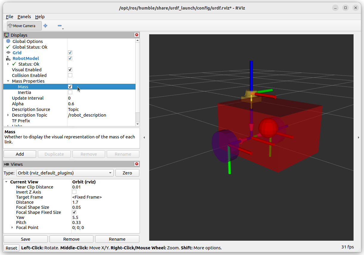
The centre of mass of the base_link box is shown as a sphere. This view can be enabled in RVIZ using the Mass Properties options. Enabling the Inertia option will show a cube which perfectly aligns with the visuals.
Remember that the collision and inertia information will become more important when we use this information for simulations.
Danger
For meshes, CAD programs etc can be used to calculate the moments of inertia, but they sometimes use a different formulation! See the official documentation for details. Some CAD software don’t even calculate it correctly! DOUBLE DANGER!
If in doubt, it is better to approximate the system as a primitive shape and use that instead.