Adding Links
The additional elements of a URDF link are all optional (visual, collison, inertial), but they are helpful in other ways beyond performing rigid body transformations.
Story Time
Humans rely on their vision for a lot of interpretation. Adding visual indicators to our robot model can be incredibly beneficial. When deploying robots and trying not to crash into anything (such as a nuclear reactor), being able to see the chassis of a mobile robot or manipulator can genuinely be the difference between a good day and a very bad day.
Adding Visuals
There are two primary ways to add visual elements to a URDF file, either through a simple primitive geometry (box, cylinder, sphere) or by adding a mesh file. To save time, we will only explore the use of primitive geometries.
Adding a visual tag to the base_link, the code below simply adds a box which is slightly offset from the base_link link. Notice we swapped a single line <link name=""/> tag to instead use opening and closing tags <link></link>.
 1<?xml version="1.0"?>
 2
 3<robot name="diff_drive_example">
 4
 5<!-- LINKS -->
 6<link name="base_link">
 7    <visual>
 8        <geometry>
 9            <!-- Box is defined as xyz lengths in m -->
10            <box size="0.5 0.4 0.3"/>
11        </geometry>
12        <!-- Centre of box relative to link -->
13        <!-- Leave as "0 0 0" for box centre at link origin -->
14        <origin xyz="0.15 0 0.10" rpy="0 0 0"/>
15    </visual>
16</link>
17
18<link name="lidar_link"/>
19<link name="wheel_left"/>
20<link name="wheel_right"/>
21
22<!-- JOINTS -->
23<joint name="base_lidar_joint" type="fixed">
24    <parent link="base_link"/>
25    <child link="lidar_link"/>
26    <origin xyz="0 0 0.3" rpy="0 0 0"/>
27</joint>
28
29<joint name="base_wheel_left_joint" type="continuous">
30    <parent link="base_link"/>
31    <child link="wheel_left"/>
32    <origin xyz="0 0.2 0" rpy="-1.5707 0 0"/>
33    <axis xyz="0 0 1"/>
34</joint>
35
36<joint name="base_wheel_right_joint" type="continuous">
37    <parent link="base_link"/>
38    <child link="wheel_right"/>
39    <origin xyz="0 -0.2 0" rpy="-1.5707 0 0"/>
40    <axis xyz="0 0 1"/>
41</joint>
42
43</robot>
Let’s keep rolling by modifying the wheel links, adding cylinders to represent the wheels. Replace lines 19 and 20 with the code below.
19<link name="wheel_left">
20    <visual>
21        <geometry>
22            <cylinder length="0.06" radius="0.1" />
23        </geometry>
24
25        <material name="uom_purple">
26        <!-- Define a colour for the link -->
27            <color rgba="0.4 0 0.6 1"/>
28        </material>
29        <origin xyz="0 0 0.03" rpy="0 0 0"/>
30    </visual>
31</link>
32
33<link name="wheel_right">
34    <visual>
35        <geometry>
36            <cylinder length="0.06" radius="0.1" />
37        </geometry>
38
39        <material name="uom_purple">
40            <!-- Define a colour for the link -->
41            <color rgba="0.4 0 0.6 1"/>
42        </material>
43        <origin xyz="0 0 -0.03" rpy="0 0 0"/>
44    </visual>
45</link>
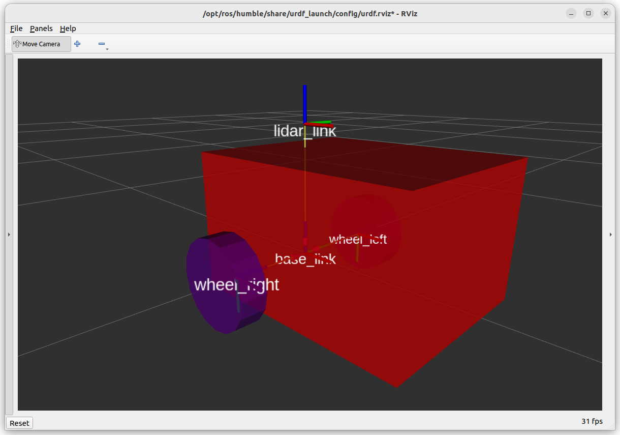
This time we have defined a colour for the link using the material tag. The cylinders have been offset using the <origin> tag, so they are outside the base_link chassis, radius 0.1m and height 0.06m.
Rebuild the package. The resulting representation should look similar to that in the picture below.
Using a Mesh File
Mesh files, such as an .stl file, can be used as a visual element. This is great for more bespoke parts of a robot and a more accurate representation.
For the lidar, please download the file /meshes/Generic_100mm_lidar, and copy it into the meshes directory.
This stl file will act as the visual element for the lidar, with more intricate features than a simple cylinder, box or sphere.
 1<?xml version="1.0"?>
 2
 3<robot name="diff_drive_example">
 4
 5<!-- Materials -->
 6<material name="uom_yellow">
 7    <color rgba="1.0 0.8 0.2 1"/>
 8</material>
 9
10<!-- LINKS -->
11<link name="base_link">
12    <visual>
13        <geometry>
14            <!-- Box is defined as xyz lengths in m -->
15            <box size="0.5 0.4 0.3"/>
16        </geometry>
17        <!-- Centre of box relative to link -->
18        <!-- Leave as "0 0 0" for box centre at link origin -->
19        <origin xyz="0.15 0 0.10" rpy="0 0 0"/>
20    </visual>
21</link>
22
23<link name="lidar_link">
24    <visual>
25        <geometry>
26            <!-- Mesh file uses "package://<packagename>/<path>" -->
27            <!-- Scale "x y z" can be useful when converting to mm <-> metres -->
28            <mesh filename="package://example_urdf_description/meshes/Generic_100mm_lidar.stl" scale="1 1 1"/>
29        </geometry>
30        <material name="uom_yellow"/>
31        <origin xyz="0 0 0" rpy="0 0 0"/>
32    </visual>
33</link>
34
35<link name="wheel_left">
36    <visual>
37        <geometry>
38            <cylinder length="0.06" radius="0.1" />
39        </geometry>
40
41        <material name="uom_purple">
42        <!-- Define a colour for the link -->
43            <color rgba="0.4 0 0.6 1"/>
44        </material>
45        <origin xyz="0 0 0.03" rpy="0 0 0"/>
46    </visual>
47</link>
48
49<link name="wheel_right">
50    <visual>
51        <geometry>
52            <cylinder length="0.06" radius="0.1" />
53        </geometry>
54
55        <material name="uom_purple">
56            <!-- Define a colour for the link -->
57            <color rgba="0.4 0 0.6 1"/>
58        </material>
59        <origin xyz="0 0 -0.03" rpy="0 0 0"/>
60    </visual>
61</link>
62
63<!-- JOINTS -->
64<joint name="base_lidar_joint" type="fixed">
65    <parent link="base_link"/>
66    <child link="lidar_link"/>
67    <origin xyz="0 0 0.3" rpy="0 0 0"/>
68</joint>
69
70<joint name="base_wheel_left_joint" type="continuous">
71    <parent link="base_link"/>
72    <child link="wheel_left"/>
73    <origin xyz="0 0.2 0" rpy="-1.5707 0 0"/>
74    <axis xyz="0 0 1"/>
75</joint>
76
77<joint name="base_wheel_right_joint" type="continuous">
78    <parent link="base_link"/>
79    <child link="wheel_right"/>
80    <origin xyz="0 -0.2 0" rpy="-1.5707 0 0"/>
81    <axis xyz="0 0 1"/>
82</joint>
83
84</robot>
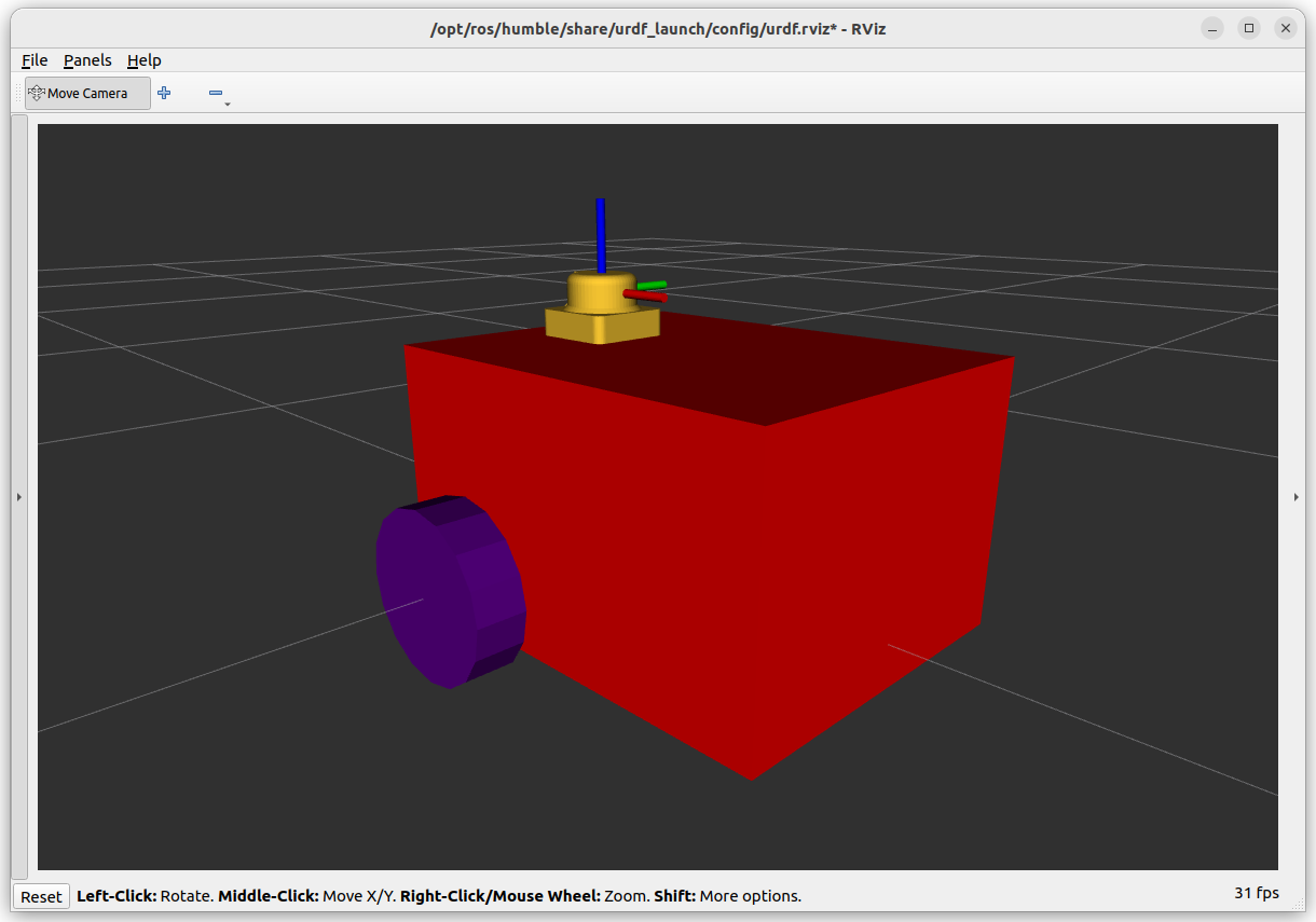
We have also added a specific material (uom_yellow) outside of tag, this means it can be reused elsewhere in the file. Rebuild the package to see image similar to below.
Where is the Castor?
Including the castor (modelled as a sphere) will be left as a stretch task. For now let’s concentrate on the final aspects behind links.